ELECTRICAL BASICS – Part 2 – AC
ELECTRICAL BASICS – Part 2 – AC
ALTERNATING CURRENT
Section 1 – BASIC DEFINITIONS
Section 2 – RESISTIVE LOADS
Section 3 – NOMINAL VALUES
Section 4 – PHASE
Section 5 – INDUCTIVE LOADS
Section 6 – CAPACITIVE LOADS
Section 7 – REACTANCE
Section 8 – IMPEDANCE
Section 9 – SERIES CIRCUIT
Section 10 – RESONANCE
Section 11 – PARALLEL CIRCUIT
Section 12 – WATTS and VOLT-AMPS
Section 13 – RECTIFIED – AC to DC
Section 14 – CONCLUSION and REFERENCES
Section 1 – BASIC DEFINITIONS
Alternating current refers to a repeating, regular, reversal of voltage direction and current flow. When the voltage pushing the current along is changing, the current, in most cases, will be found to be changing in a similar fashion.

If the load is purely a resistance type of load, such as a heating element, it will be found that the current through the load will reach its peak value (IPEAK) just as the voltage reaches its peak. As the voltage alternates from its positive maximum or peak value (VPEAK), to its minimum value (-VPEAK), the current will do the same. The current will diminish as the voltage diminishes and will reach its lowest value (-IPEAK) exactly as the voltage reaches its lowest value (-VPEAK).
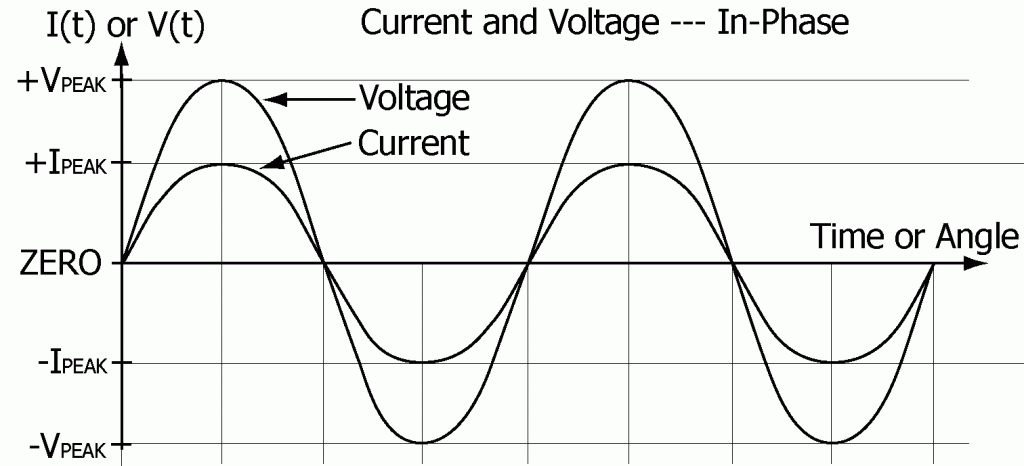
For a purely resistive load (resistance only), the current being pushed through the load varies just as the voltage varies. At any instant, the current is exactly proportional to the voltage being applied to the load, just as is stated by Ohm’s law (V = IR).
A negative voltage means that the direction the voltage is pushing is opposite to the direction it would be pushing if the voltage were positive.
A negative current means the direction the current is flowing is opposite to what it would be if the current were positive.
The result of applying an alternating voltage to a resistive load is an alternating current flowing back and forth through the load, rising and falling, peaking and reversing, exactly in step with the applied voltage.
The term Alternating Current (Abbreviated ac or AC) commonly refers to both alternating voltages and alternating currents. For a commercial power system, saying that a source of power is AC really means that the power source is an alternating voltage source. There may be no current flow at all, but the source is still called an Alternating Current (AC) source.
The behavior of the current from an alternating voltage source, its relationship to the voltage being applied, and the power being consumed is the subject of this paper.
Here are a few definitions that will be needed before going further.
Variable: A number or quantity that may vary and assume an entire range of values. The alternating voltage (V) and current (I) above are variables. Their values change from moment to moment.
Function: A quantity whose value depends on the value of some other factor, factors, quantities or variables. (Example: price is a function of supply and demand.)
AC voltage is a function of time, as is AC current. The values of these variables change from moment to moment as time moves along. Each can be said to be a function of time.
In order to indicate that the variable voltage (V) is a function of time (t), the voltage is written in the form V(t). The written symbol V(t) represents that the variable V is a function of time. When speaking, V(t) is commonly verbalized by saying “Voltage as a function of time” or simply “V of t”.
V(t) is also known as the instantaneous value of the voltage V. The voltage may depend upon other factors than just time, but writing V(t) rather than just V clearly indicates that V is a function of time and that one is talking about the instantaneous value of the voltage V as it changes in time, rather than perhaps some average or effective value of V.
Cycle: a complete set of events that repeats – a periodically repeated sequence of events.
Cyclic: Having the nature of repeating. Cyclic implies that the sequence of events repeats.
One Cycle: The minimum complete set or sequence of events which having once occurred will be repeated identically with the new starting point being the end point of the preceding cycle.
Two examples of one cycle are indicated on the preceding drawing of an alternating voltage. The starting point of a cycle need not be only at a peak or zero as drawn. Any point can be designated as the starting point of a cycle.
Periodic: Having the nature of repeating regularly or uniformly.
Alternating voltage is a periodic phenomenon. The sequence repeats regularly and uniformly in time.
The dotted line painted on a highway is an example of a phenomenon that is periodic in space.
Periodic Function: A function that repeats itself regularly or uniformly.
Alternating voltage is a periodic function of time.
The dotted line painted on a highway is a periodic function of position.
Period: The length of time required for a periodic function or event to repeat itself – the duration of one complete cycle or oscillation.
The period of an alternating voltage is the length of time required to complete one cycle.
The period of the dotted line on the highway could be said to be the distance between identical points in the repeating pattern of dots and spaces. This is a similar concept, but the word “period” most usually refers to time intervals only. Seldom is the period of any phenomena taken to mean other than the time required for the phenomenon to repeat once.
Frequency: The rate at which a particular phenomenon or sequence of events repeats.
Frequency is measured in cycles per second. (Abbreviated cps)
The term “hertz” (Abbreviated Hz) meaning cycles per second (cps), has since been adopted internationally to replace the term cycles per second as the basic unit of frequency. Named in honor of Heinrich Rudolph Hertz, (1857-1894), a German Physicist, for his research and discoveries regarding radio waves and their transmission, circa 1887.
The period (T) in seconds of a periodic function of frequency (f) in cycles per second or hertz is given by this formula
T = 1 / f .
If the frequency of the alternating voltage pictured earlier were 60 cycles per second (60 Hz) then the cycle would repeat 60 times per second. Thus the period or duration of a single cycle would be 1/60 of a second with the voltage swinging equally to the positive and negative extremes about zero.
As a side note, in some parts of the world the available power is 50 cycles per second.
Section 2 – RESISTIVE LOADS
Resistive: Of, pertaining to, or having to do with resistance.
Resistive Load: Any load that behaves as if its only electrical quality were resistance.
For an alternating voltage V(t) pushing a current I(t) through a resistance R, the current at any instant will be proportional to the amount of push (voltage) being applied at any instant. Ohm’s law gives the relationship between I(t) and V(t).
V(t) = I(t) x R
For an alternating voltage V(t) pushing a current I(t) through a resistance R, the power or rate of energy delivery at any instant, P(t), will be equal to the product of the voltage at that instant times the current at that instant.
P(t) = V(t) x I(t)
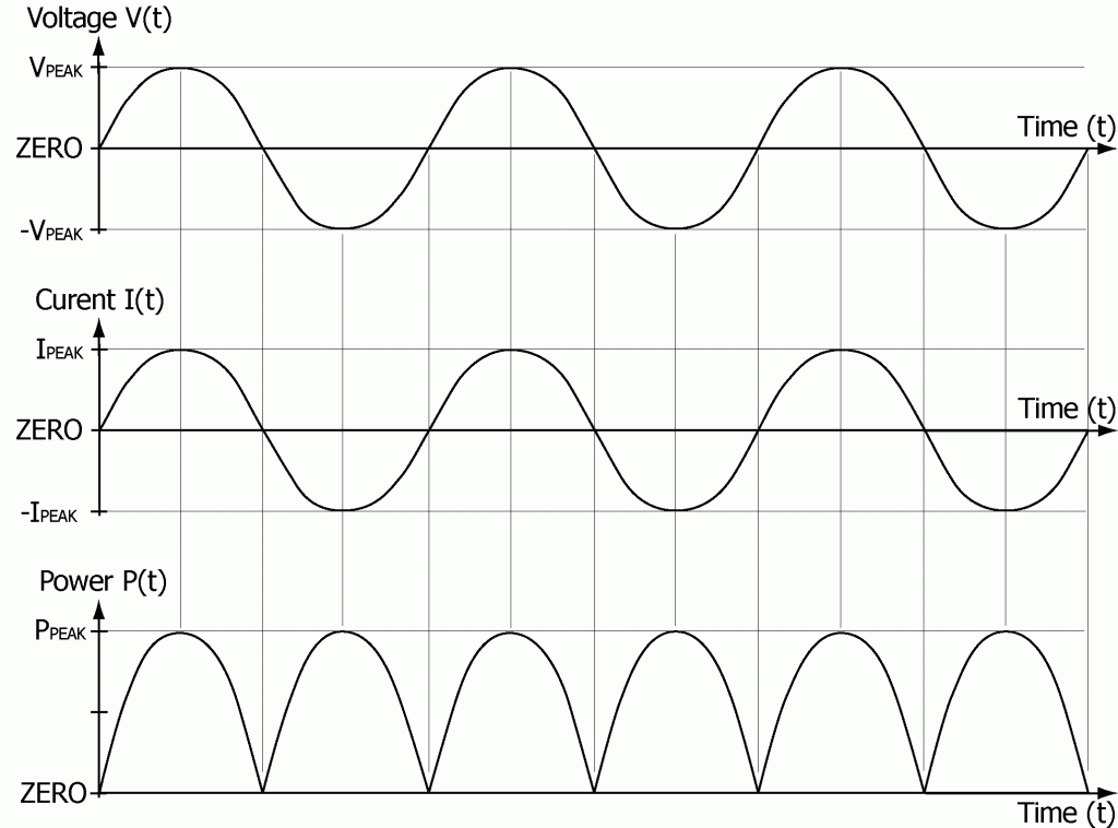
The rate of delivery of energy changes from moment to moment as the current and voltage change. With a resistive load the current reaches its peak at exactly the same instant the voltage reaches its peak and so the power reaches its peak at that same instant.
This relationship between power, current, and voltage can be further simplified by substituting I(t) x R for V(t) in the formula for power:
P(t) = V(t) x I(t) = I(t) x R x I(t) = I(t)2 x R = I(t)2R
P(t) is zero when the current is zero. P(t) is at its maximum or peak value (PPEAK) twice per cycle, once when the current is at its maximum value (IPEAK) and once again when the current has turned around and reached its minimum (-IPEAK). -IPEAK is I(t)’s peak value in the negative direction.
PPEAK = IPEAK2R = (-IPEAK)2R
Next is a sketch of V(t), I(t), and P(t) for a purely resistive load.
In a situation where the load is not changing, the power (P) being delivered to the load is equal to the average rate at which energy is being delivered during a full cycle.
P = the average of P(t)
= the average of I(t)2R
= R times the average of I(t)2.
Because the words “mean” and “average” are equivalent terms mathematically, by substituting the word “mean” for the word “average” a new concept can be developed along with an explain for its name. The concept is known as the RMS value of the current (IRMS)
Using this RMS value for the current, the formula for AC power can be written just as it is for DC power, and the following equation which defined IRMS must be true:
IRMS2R = R times the average of I(t)2 .
Dividing both sides of the equation by R yields
IRMS2 = the average of I(t)2 .
Substituting the word “Mean” and taking the square root of both sides yields
IRMS = the square Root of the Mean value of the Square of I(t)
= the Root Mean Square of the current
= the RMS current.
This is the genesis of the term “RMS”. This concept is used throughout discussions of electrical power. However, not so always does one even write or mention the label “RMS” when speaking of AC currents. It is generally understood that the RMS value of the current is being used unless otherwise specified.
The relationship between the RMS value of the current (IRMS) and the peak value of the current (IPEAK) comes from the following two points.
First, by definition the RMS current is defined as being that specially averaged value of the current in an AC circuit, which when squared and then multiplied times the resistance of the circuit, gives the correct and actual average value of the power being delivered to the resistance.
P = IRMS2R
Second, by experiment and mathematical computation the average value of the power delivered to a resistance has been found to be one half of the value of the peak power in any cycle:
P = ½PPEAK = ½IPEAK2R.
This gives the following relationship between the RMS value of the current (IRMS) and the peak current (IPEAK).
½IPEAKR = IRMS
Dividing both sides of the equation by R yields
I = ½IPEAK
Taking the square root of both sides yields
IRMS = the square root of (½IPEAK2)
= √(½IPEAK2)
= (√½)IPEAK.
( √2 = 1.4142… and √½ = 0.7071… )
The value of IRMS is now defined in terms of the measurable quantity IPEAK.
IRMS = 0.707 IPEAK

RMS current: The effective value of an AC current.
The RMS value of an AC current is defined so that the same amount of power would be consumed by pushing either the RMS value of AC current through a resistance (R) or an equal value of DC current through that same resistance (R).
RMS voltage: The effective value of an alternating voltage.
The RMS voltage is defined so that the RMS value of the voltage across the load (VRMS) is related to the RMS current through the load (IRMS) by Ohm’s law.
VRMS = IRMSR
Substituting IRMS = 0.707 IPEAK and VPEAK = IPEAKR in this equation gives the value of VRMS in terms of the measurable quantity VPEAK.
VRMS = IRMSR = 0.707 IPEAKR = 0.707 VPEAK
The power supplied to the load is as before, given by the product of the RMS value of the voltage across the load times the RMS current of through the load.
P = VRMSIRMS
The RMS value of an alternating voltage is defined so that the same amount of power would be consumed by applying either an RMS value of alternating voltage or an equal value of DC voltage across a resistance.
It would make no difference if a standard 100-watt light bulb were connected to a 120 volt DC voltage source or to a 120 volt RMS AC voltage source. A DC current equal to an AC RMS current value would produce equal power outputs from the same lamp.
Current and voltage meters are designed to display the RMS values of current and voltage.
The power being delivered to or consumed within a resistance load is given by
P = VRMSIRMS = IRMS2R.
When speaking of AC currents and voltages, it is usual to not even mention that the RMS value is being referred to. It is generally understood that RMS values are always used unless otherwise specified.
In accordance with general usage, IRMS and VRMS will be written without subscripts unless clarification is needed to avoid confusion (“I” generally stands for the RMS value of the current and “V” generally stands for the RMS value of the voltage). Peak values will still be specially marked and indicated. Instantaneous values will be specially marked whenever any clarification is needed in a discussion.
Section 3 – NOMINAL VALUES
Standard household electric power is often called 120 volts. If it were exactly 120 volts RMS, the peak voltage would be 169.7 volts.
Actual voltages vary depending on location and time of day. Such variations are due to loads that change as factories, offices, stores and households get active, start work and later shut down. The demand for power changes as heating, cooling, lighting, and other needs change. This results in varying amounts of voltage drop in different parts of the power delivery system.
A 120 volt supply system is often called a 110 or a 115 volt system. This is just three different names for the same thing. 110, 115, and 120 are known as nominal values of the voltage, a stated or specified voltage used as a name. However, these values are not necessarily the actual values of the voltage. The same is true for 240 volt power that is often also called 220 or 230 volt power.
If one were to measure the actual voltage with a volt meter the result for a typical “120 volt” supply would be around 125 to 130 volts. For a “240 supply” the result would typically be around 250 to 260 volts.
Section 4 – PHASE
Phase: A particular stage or degree of advancement of a periodic function or phenomenon, measured from some arbitrary starting point, often expressed as an angle, and measured in degrees with one full cycle being 360 degrees as in a full circle.
At the arbitrarily chosen beginning point of a cycle the phase angle would be zero. At one quarter of the way through a cycle the phase angle would be 90 degrees.
Phase Difference: The angular relationship between identical points of two periodic functions such as an AC current and an AC voltage. The angular difference between the position of the peaks of the two waves or patterns is a measure of their phase difference.
If the voltage and the current are of the same frequency and are perfectly in-phase with each other they are said to have a phase difference of zero degrees. If for instance, the voltage were to reach its peak 10 degrees ahead of the current, the voltage would be said to lead the current by 10 degrees. This is equivalent to saying that the current lags the voltage by 10 degrees.
Loads, which are not purely resistive, can cause the current to either lead or lag the applied voltage by up to 90 degrees, depending on the characteristics of the load. Loads, which contain either capacitance or inductance or some combination of both can cause the current and voltage to peak at different times.
The phase shift is said to be positive for predominantly inductive loads (voltage leads the current) and negative for predominantly capacitive loads (voltage lags the current). Mixed combinations of inductive, capacitive, and resistive ingredients can result in a phase shift anywhere from +90 degrees to –90 degrees depending on the exact mixture.
A positive phase difference means the voltage is leading the current or the current is lagging the voltage. Similarly, a negative phase difference means the voltage is lagging the current or equivalently the current is leading the voltage.
The concept of angular relationship can be seen in following example. An alternating voltage will result from simply rotating a coil of wire within a magnetic field. The next drawing shows the relationship of the output voltage from the coil to the orientation of the coil within the magnetic field as the coil rotates.
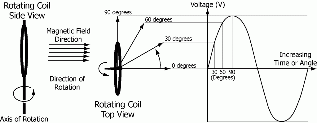
The curved arrows indicate the direction of rotation. The angle of rotation of the coil is marked on the voltage graph to correspond to the coil orientation at the instant of that voltage. The direction of the magnetic field in which this coil is rotating is horizontal.
The output voltage from the rotating coil is a regularly oscillating waveform called a sine wave. At any instant in time the output voltage from the steadily rotating coil is directly related to the physical orientation of the coil relative to the magnetic field.
“Sine” is a simple mathematical function of angle. The function “Sine of angle A” is written in the form “sine(A)” but more commonly in the form “sin(A)”. Tables giving values of sin(A) for angle “A” ranging from 0 to 90 degrees can be found in numerous math and science books. If one knows the size of angle A then it is not difficult to look up the value of sin(A).
The following describes the behavior of sin(A) as angle A increases through a full cycle.
Sin(A) is defined as the ratio of the length of side “a” to the length of side “c” of the right angle triangle drawn below.
Sin(A) = a/c
Uppercase letters “A”, “B”, and “C” are angles and are understood to be the names of the angles in addition to numerically being the sizes of the angles.
Lowercase letters “a”, “b”, and “c” are the sides and are understood to be the names of the sides in addition to numerically being the lengths of the sides.
Side “a” is opposite angle “A”
Side “b” is opposite angle “B”
Side “c” is opposite angle “C”
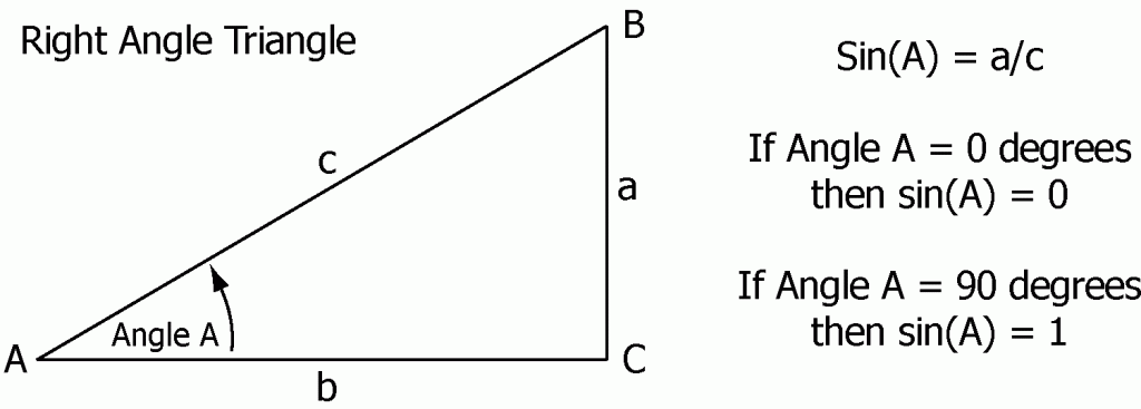
When side “a” approaches zero length, angle “A” approaches 0 degrees, and sin(A), the ratio of “a” to “c”, approaches zero.
As the length of side “a” increases, angle “A” approaches 90 degrees, lengths “a” and “c” become closer to equal, and sin(A), the ratio of “a” to “c”, approaches the value 1.
As angle “A” increases beyond 90 degrees, both the length of side “a” and the value of sin(A) will begin to decrease.

As angle “A” approaches 180 degrees, both the length “a” and sin(A) will approach zero.
As angle “A” increases beyond 180 degrees side “a” extends downward from the base line and thus becomes negative. Sin(A) = a/c becomes negative. (“a” is a distance measured from the horizontal baseline. Up is positive and down is negative. “c” is a length only and has no positive or negative direction.
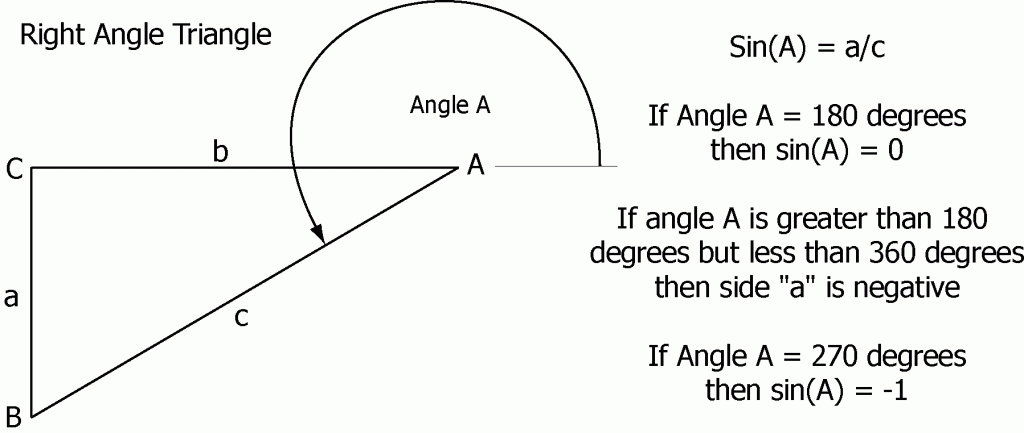
As angle “A” approaches 270 degrees, the length of “a” extends and approaches the length of “c” so that sin(A) = a/c approaches the value -1.
As angle “A” increases beyond 270 degrees, both the length of side “a” and the magnitude of sin(A) begin to decrease. Side “a” remains negative, meaning that “a” extends downward from the base line and sin(A) remains negative as well.
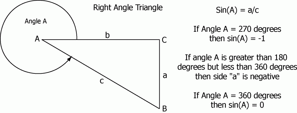
As angle “A” increases toward 360 degrees, completion of a full rotation, the length of side “a” again approaches zero. And so sin(A) approaches zero from the negative, and the cycle nears completion.
The function sine of angle “A” repeats every 360 degrees. This is a picture of what sin(A) looks like as angle “A” increases steadily from zero.
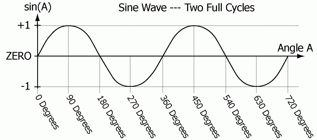
Sine of angle “A” ranges between -1 and +1. If sin(A) were multiplied by the peak value of the current (VPEAK) the result would be a sine wave ranging in value from -VPEAK to +VPEAK. Similarly for the current I(t) if sin(A) were multiplied by the peak value of the current (IPEAK).
The phase or phase angle at a specific point in any cycle of a periodic function, is the angle which corresponds to that specific point of the cycle, measured from whatever was chosen as the starting point of the cycle.
When speaking of two periodic functions of the same frequency, the amount by which one variable leads or lags the other is called the phase difference or relative phase difference of the two functions.
As an example, consider two periodic functions of the same frequency, a current moving through a load because of the AC voltage being applied to the load. If in each cycle the current peaks 20 degrees after the AC voltage peaked then the current would be said to lag the voltage by 20 degrees. The reaction of the load upon the alternating current has shifted the phase of the current being pushed through the load by 20 degrees relative to the phase of the applied voltage. The phase of the applied voltage would remain unchanged, locked in step with the generator that create it and unaffected by the load provided the source were capable of delivering the current in an unaffected manner. This defines a perfect voltage source, able to supply unlimited power without adverse consequence.
If the phase of the current passing through the load is not shift from the phase of the applied voltage then the current and voltage would be said to be “in-phase”.
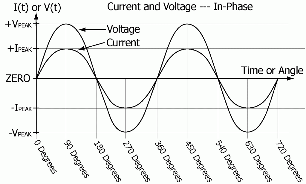
Up to this point Ohm’s law and the formula for power has only been applied to purely resistive loads. The importance of considering only resistive loads has been that for a purely resistive load the current passing through the load is always proportional to the voltage applied. Thus Ohm’s law applies exactly and can be called law. The current always changes exactly as the applied voltage changes.
Resistive: Of, pertaining to, or having to do with resistance.
Resistive Load: Any load which behaves as if its only electrical quality were resistance, as determined by observation and measurement of the relationship of the phase of the applied voltage to the resultant phase of the current passing through the load. A purely resistive load will not cause the current to either lag or lead the voltage. The current stays in-phase with the voltage.
When the current is not changing exactly as the applied voltage and no longer peaks and passes through zero exactly as the voltage changes then Ohm’s law would no longer apply as it has in the earlier discussions. This is a new realm of electrical effects and consequences.
Under certain circumstances, for certain types of loads, the alternating current and the alternating voltage of a load will not be in-phase. The current flowing through the load may be forced to either lead ahead of the applied AC voltage or lag behind. The degree of lead or lag may be anywhere from –90 degrees to +90 degrees depending on the type of load through which the AC current is passing.
Current lead and lag are reactions. For an isolated system consisting of only one load and a perfect AC voltage source, only the AC current flowing through the load, not the AC voltage applied to the load, would have its phase shifted.
A complex load, with multiple elements of various types connected in various ways, the voltage applied to the various elements within the load can also have its phase shifted by different amounts. Such combinations can be considered as a single load with voltage phase shifts occurring within the load as an internal phenomenon. This could be similar to viewing a whole factory or even a whole city as a single load. Externally the voltage applied to the load could remain unaffected by the load and only the current would have its phase shifted. This assumes a perfect voltage source, equivalent to the load being insignificant relative to the ability of the voltage source to deliver power.
Section 5 – INDUCTIVE LOADS
Current Lag: The alternating current flowing through a load will LAG behind the alternating voltage applied to the load when the load is inductive or has predominantly inductive characteristics. Resistance within the load moderates the degree of current lag but causes neither lead nor lag. An inductive load will cause the current to peak and begin to decline after the voltage has peaked and begun to decline. This is due to the reactive characteristic of inductance.
Inductive: Of, pertaining to, or having to do with inductance.
Inductance: That property of a circuit or component of a circuit which by means of magnetic field effects opposes the flow of alternating or changing currents through that circuit or circuit component. (Generally represented by the symbol L)
The unit of inductance is the henry. One henry is the amount of inductance that would produce an opposing voltage of one volt when the current flow through the coil or inductor is increasing or decreasing at the rate of one ampere per second.
Named in honor of the American physicist Joseph Henry (1797 – 1878) a physicist from the United States, noted for his extensive research and advances regarding magnetic induction circa 1831. (Abbreviated h)
Inductor: A device used to impede the flow of alternating current by means of inductance. Inductors are commonly made of wire wound into spiral or coil shapes.
Inductance increases in proportion to the number of turns of wire or windings used to form the coil. The amount of inductance can be greatly increased at low frequencies (like 60 Hz) by forming the coil about a “soft” magnetic material such as Iron. A “soft” magnetic material is a one that is easily magnetized and demagnetized.
Inductive Load: A load that to some degree causes the phase of the current flowing through the load to lag behind the applied voltage.
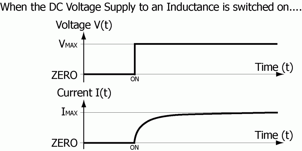
Direct currents are unaffected by inductance. This is true except for when the current flow is changing. Inductance opposes any change in current flow. As an example, when a constant voltage source is first connected to an inductance, the current through the load will rise as shown below. This drawing assumes that the applied voltage is VMAX, that the inductor’s internal resistance (RINTERNAL) is the only resistance in the circuit, and that RINTERNAL is sufficient to limit the maximum current through the inductor to IMAX.
IMAX = VMAX / RINTERNAL
Section 6 – CAPACITIVE LOADS
Current Lead: The alternating current flowing through a load will lead the alternating voltage applied to the load when the load is capacitive or has predominantly capacitive characteristics. Resistance within the load moderates the degree of lead but again causes neither lead nor lag. A capacitive load will cause the current to peak and begin to decline before the voltage has peaked and begun to decline. This is caused by the reactive characteristics of capacitance.
Capacitive: Of, pertaining to, or having to do with capacitance.
Capacitance: That property of a circuit or component of a circuit that allows electrical energy to be stored when electrical charge is pushed into one area of the capacitance and is stored while an equal amount of electrical charge is pushed out of or away from the opposing area of the capacitance. The ability to store electrical energy by accumulating charge in this manner in proportion to the voltage difference between the two areas alters the behavior and flow of current that would try to pass by or through the capacitance. (Generally represented by the symbol C)
Capacitance is the measure of the amount charge (Q) that can be stored within a device as a result of applying a constant DC voltage (V) to the device. The capacitance of the device is equal to the ratio of the amount of charge stored within the device to the voltage applied to the device.
C = Q / V
The unit of capacitance is the farad. One farad is the amount of capacitance that with one DC volt applied would hold one coulomb of electric charge.
Named in honor of Michael Faraday (1791 – 1867) an English physicist and chemist, for his extensive research and advances regarding electric and magnetic effects circa 1831. (Abbreviated f)
Capacitor: An electrical device consisting of two conductive plates in relatively close proximity to each other, separated by air or some other type of insulating material. The capacitance increases as the amount of conductive surface in close proximity increases and as the closeness increases.
The type of dielectric (insulating material) used in a capacitor can greatly increase the capacitance because of the interaction of the material with the charge which accumulates on the conductive surfaces within the capacitor. The interaction of the dielectric material with the charge on the conductive surfaces can neutralize or decrease the net effect of the charge residing within the capacitor thus allowing more charge to be added without increasing either surface area or the applied voltage. This effect depends on the type of dielectric material.
Capacitive Load: A load which to some degree causes the phase of the current flowing through the load to lead ahead of the applied voltage.
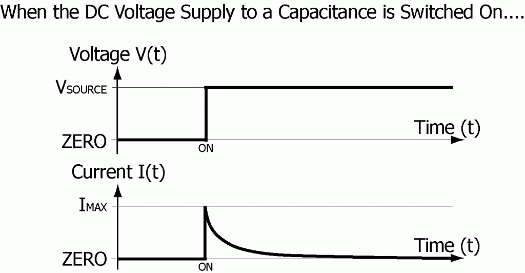
Direct currents are unable to pass through capacitance. The Capacitor just fills with charge until it is holding all it can at whatever voltage is being applied. For example, if a voltage source were connected directly to a capacitance, the current would rise to its highest level almost immediately, limited only by the internal resistance and inductance of the device.
For the following example it is assumed that these two internal factors are negligible. A resistance (R) could be placed in series with the capacitor to limit the inrush current to
IMAX = VSOURCE/R.

When the steady DC voltage (VSOURCE) is first connected to this series combination, the voltage across the capacitor (VC) would be zero for there would be no charge stored within the capacitor (VC = Q/C). The applied voltage (VSOURCE) would be entirely across the resistor causing the initial current through the resistor to be IMAX = VSOURCE/R.
As current flows into the capacitor the voltage across the capacitor (VC) increases in proportion to the amount of charge stored within the capacitor and the voltage across the resistor (VR) decreases. The decreased voltage across the resistor then pushes less current through the resistor and into the capacitor. Eventually the capacitor would be fully charged, the voltage across the capacitor would be equal to the source voltage, and no additional current would flow as is shown in the following sketch.
Section 7 – REACTANCE
Reactance: The ability to impede, oppose, or otherwise affect the flow of an alternating current through a load or element of a load. Both inductance and capacitance react to AC currents. Resistance does not. Reactance is measured in ohms. (Generally represented by the symbol X)
Inductive Reactance: Opposition to the flow of alternating current through a circuit or load, due to the inductance of that circuit or load. (Generally represented by the symbol XL)
The reactance of an inductor is measured in ohms and increases in proportion to the frequency (f) in hertz of the applied voltage and the inductance (L) in henrys.
XL = 2πfL
(A larger inductance yields a larger reactance.)
(π = pi = 3.1416 approximately)
Ohm’s law gives the current flow through an inductance (L):
IL = V / XL
Inductive reactance by itself, will cause the current to lag 90 degrees behind the applied alternating voltage. Resistance added to the inductance, will reduce the phase shift caused by the inductance. Capacitance added to the inductance can totally counter the phase shift effects caused by the inductance.
Capacitive Reactance: Opposition to the flow of alternating current through a circuit or load, due to the capacitance of that circuit or load. (Generally represented by the symbol XC)
The reactance of a capacitor is measured in ohms and increases inversely as the frequency (f) in hertz of the applied voltage and the capacitance (C) in farads.
XC = 1/(2πfC)
(A larger capacitance yields a smaller reactance.)
Ohm’s law gives the current flow through a capacitance (C):
IC = V / XC
Capacitive reactance by itself, will cause the current to lead 90 degrees ahead of the applied alternating voltage. Resistance added to the capacitance, will reduce the phase shift effects caused by the capacitance. Inductance added to the capacitance can totally counter the phase shift effects caused by the capacitance.
The reactive effects of inductance and capacitance can actually cancel each other completely and result in a purely resistive load characteristic causing no phase shift. When an inductor and capacitor are connected in series the combined reactance (X) of the two is equal to the inductive reactance (XL) less the capacitive reactance (XC).
X = XL – XC
Section 8 – IMPEDANCE
Impedance: The combined, total opposition offered by a circuit or an element of a circuit to the flow of an AC current through that circuit or element. This includes the combined effects of Resistance, Inductive Reactance, and Capacitive Reactance. (Generally represented by the symbol Z)
Ohm’s law gives the relationship of AC current to voltage in a combination load just as it did for DC systems. However, the impedance (Z) is used in place of the resistance (R). Thus Ohm’s law for AC circuits for both the instantaneous and the RMS values of current and voltage involving resistive and reactive elements becomes:
V = IZ I = V/Z Z = V/I
The impedance of a combination of reactive and resistive circuit elements is not simply the sum of the individual resistances and reactances. Analysis of exactly how inductive reactance combines with capacitive reactance and also with resistance to give the total impedance of a circuit or load requires separate analysis of both parallel and series combination loads. This is next.
Section 9 – SERIES CIRCUIT
In this section the source voltage (VSOURCE) is causing the current (I) to flow through this combination of reactive and resistive circuit elements connected in series:

Essential to circuit analysis is Kirchhoff’s first rule.
Kirchhoff’s first Rule: (also known as Kirchhoff’s Point Rule) At any junction point within an electrical circuit, the sum of currents flowing towards that point is equal to the sum of the currents flowing away from that point. A junction point is defined as any location in a circuit where two or more conductors are joined together.
Kirchhoff’s first rule assumes the following:
1. Electric charge is neither being created nor destroyed within any junction point or conductor. This is a specific application of the principal of conservation of electric charge, that electric charge is neither created nor destroyed.
2. The density of electric charge within the conductors and the junction points remains constant. The strength of the electric forces within conductors does not allow charge to build up because of the extreme repulsive electric forces between areas of like electric charge that disperse even the slightest buildup of charge and keep the density of charge uniform. (Capacitance does allow electric charge density to increase within the area where the capacitance exists. But this is not within the conductors and junction points external to the capacitor where this rule will be applied in this paper.)
The instantaneous current flowing through the series circuit is the same throughout the circuit.
Whatever enters the resistor leaves the resistor and must continue on. Out of the resistor and into the capacitor is how the current flows. Charge can build up within the capacitor (one side building up negative charge as the other side swings positive and then back and forth). But for every electron that flows into one side of the capacitor one will flow out the other. No net charge will be built up. And whatever comes out flows through the inductor. No other route for current exists in this circuit. The instantaneous current through the series circuit is the same through each part of the circuit.
Example: Assume that IRMS = 5 amps, R = 8 ohms, XC = 2 ohms, and XL = 8 ohms.
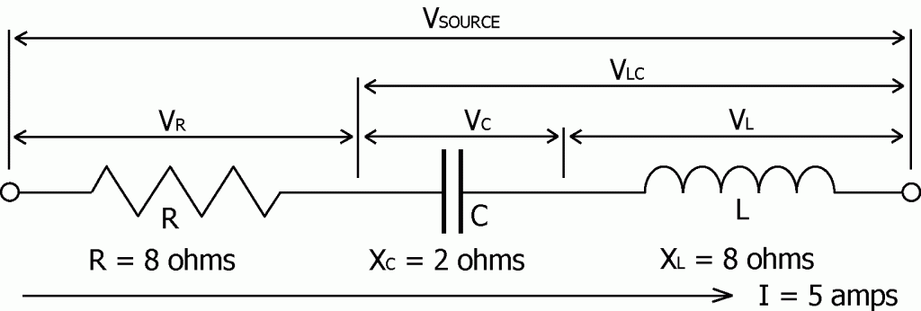
Question: As a result of the 5 amp current flowing through this series LRC circuit, what voltages will be found across the individual elements of the circuit?
Since the AC current flowing through this circuit is the same at all points throughout the circuit, the phase of the voltage gets shifted relative to the phase of the current.
The voltage across resistance (R) is VR = IR = 40 volts.
(VR is in-phase with I.)
The voltage across capacitance (C) is VC = IXC = 10 volts.
(VC lags I by 90 degrees.)
The voltage across the inductance (L) is VL = IXL = 40 volts.
(VL leads I by 90 degrees.)
Due to the reactive nature of the inductive and capacitive elements of this circuit, the simple sum of the voltages across each part of the circuit is NOT equal to (≠) the source voltage.
VSOURCE ≠ VR+VC+VL = 40+10+40 = 90 volts
Question: What has happened?
The AC voltage across a pure resistance is in phase with the current passing through the resistance.
The AC voltage across a pure capacitance lags the current passing through the capacitance by 90 degrees.
The AC voltage across a pure inductance leads the current passing through the inductance by 90 degrees.
As a result, the voltage across the inductance is 180 degrees out of phase with the voltage across the capacitance. Thus the voltage across the capacitive reactance subtracts from the voltage across the inductive reactance and the resultant combined voltage (VLC) remains 90 degrees out of phase with the current.
VLC = VL – VC = 30 volts
VLC will lead the current by 90 degrees if VL is greater than VC.
VLC will lag the current by 90 degrees if VL is less than VC.
Since the voltage across the combined reactance is 90 degrees out of phase with the current it must also be 90 degrees out of phase with the voltage across the resistance. As a result the voltages (VR and VLC) combine just as the lengths of the sides of a right angle triangle would add to give the length of the resultant third side.
VSOURCE = √[VR2 + (VL – VC)2] = √(402 + 302) = √2500 = 50 volts
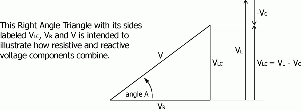
The phase of the voltage (V) relative to the source current is given by
Sin(A) = VLC /V = (VL – VC)/V = 30 / 50 = 0.60
Phase angle A = +36.9 degrees
The voltage leads the current by 39.6 degrees.
Starting with the solution V2 = VR2 + (VL – VC)2 and substituting these values for the voltages ( V = IZ, VR = IR, VC = IXC, and VL = IXL with I being the same at all points within the circuit) the equation for Z can be found:
V2 = VR2 + (VL – VC)2
(IZ)2 = (IR)2 + (IXL – IXC)2
I2Z2 = I2[R2 + (XL – XC)2]
Z2 = R2 + (XL – XC)2
Or as a square root,
Z = √[R2 + (XL – XC)2] .

The total reactance is
X = XL – XC = 6 ohms.
The total impedance is
Z = √[R2 + (XL – XC)2] = √[82+6]2 = √100 = 10 ohms.
The applied voltage is therefore
V = IZ = 5 amps x 10 ohms = 50 volts.
The 5 amp current flowing through this series circuit example will lag the source voltage by approximately +36.9 degrees as is shown in the next drawing.
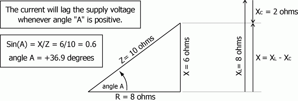
Whenever angle “A” is positive the current will lag the supply voltage.
Whenever angle “A” is negative the current will lead the supply voltage.
Section 10 – RESONANCE
As demonstrated above the total impedance of a combination series circuit is given by
Z = √[R2 + (XL – XC)2].
Notice that when XL = XC the impedance of the series will be at its minimum value. Since XL increases with increasing frequency and XC decreases with increasing frequency there must exist a frequency at which the inductive reactance (XL = 2πfL) will equal the capacitive reactance (XC = 1/[2πfC]). This gives the following equation that is true at the resonant frequency:
XL = XC
2πfL = 1/(2πfC)
To find the frequency at which XL = XC, multiply both sides of the equation by f/2πL then take the square root of both sides. This yields
f = 1/[2π√(LC)] = 0.159/√(LC).
The frequency at which the effects due to inductance exactly cancel the effects due to capacitance is known as the resonance frequency of the circuit. At the resonance frequency the impedance of the series circuit will be equal to the resistance alone, the current flow through the circuit will be at its maximum possible value, and the current flowing through the circuit will be in-phase with the applied voltage.
IMAX = VSOURCE / R
Question: In the series circuit example, what would happen if the source voltage frequency were changed to a value where resonance was achieved (XL = XC)?
If the frequency were cut in half then XL would be cut in half, from 8 ohms to 4 ohms, and XC would double, from 2 ohms to 4 ohms. R would remain 8 ohms and XL would equal XC.
X = XL – XC = 0
Z = 8 ohms
I = VSOURCE / Z = 50 volts / 8 ohms = 6.25 amps
VR = IR = 50 volts
VC = IXC = 25 volts
VL = IXL = 25 volts
Phase angle A = 0 degrees = no phase shift
Section 11 – PARALLEL CIRCUIT
In this section the source voltage (V) is causing the current (I) to flow through this combination of reactive and resistive circuit elements connected in parallel:

The instantaneous source voltage (V) applies equally to all elements of the circuit.
Question: What can be said about the currents in this circuit?
The supply current (I) may be out of phase with the supply voltage (V). The actual amount will depend upon the sizes and phases of the individual currents (IR, IL, and IC) and their individual phases relative to the supply voltage.
The current flowing through the resistor is IR = V/R.
(IR is in-phase with V)
The current flowing through the inductor is IL = V/XL.
(IL lags V by 90 degrees)
The current flowing through the capacitor is IC = V/XC.
(IC leads V by 90 degrees)
Kirchhoff’s first rule states that at any junction point within an electrical circuit, the sum of currents flowing towards that point is equal to the sum of the currents flowing away from that point. Let’s apply that to the junction point where IL and IC combine and form ILC.
The current flowing into the capacitance is fully 180 degrees out of phase with the current flowing into the inductance. As a result, at the junction where ILC splits to form IL and IC, the current IC is always flowing exactly opposite to IL, away from the junction whenever IL is flowing toward the junction. The current IL gives a positive contribution to ILC while the current IC takes away from ILC. The combined current ILC equals the difference IL minus IC and remains 90 degrees out of phase with IR.
ILC = IL – IC
ILC will lag IR by 90 degrees if IL is greater than IC.
ILC will lead IR by 90 degrees if IL is less than IC.
The current (ILC) passing through the combined reactance is 90 degrees out of phase with the current (IR) passing through the resistance. As a result the currents ILC and IR combine just as the lengths of the sides of a right angle triangle would add to give the length of the resultant third side.
I2 = IR2 + (IL – IC)2
Or as a square root
I = √[IR2 + (IL – IC)2].
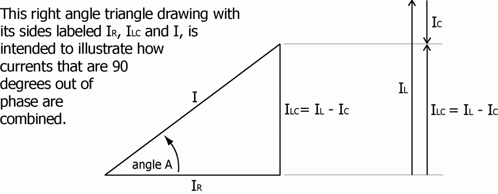
Example: Assume that V = 50 volts, R = 8 ohms, XL = 2 ohms, and XC = 8 ohms.

The current flowing through the resistor (R) is
IR = V/R = 50 volts/8 ohms = 6.25 amps
The current flowing through the inductor (L) is
IL = V/XL = 50 volts/2 ohms = 25 amps
The current flowing through the capacitor is
IC = V/XC = 50 volts/8 ohms = 6.25 amps
The total current flowing into the parallel circuit is
I = √[IR2+(IL – IC)2] = √[6.252+(6.25–25)2] = √390.7 = 19.8 amps
Therefore the impedance of the total circuit is
Z = V/I = 50 volts/19.8 amps = 2.53 ohms
And the phase of the current (I) relative to the source voltage is given by
Sin(A) = ILC/I = (IL – IC)/I = 18.75/19.8 = 0.947
Phase angle A = +71.26 degrees
The current flowing into the parallel circuit lags the supply voltage by 71.26 degrees.
Question: What would happen if the capacitance were increased in order to decrease XC and make it equal to XL? (Since XC = 1/(2πfC), increasing C decreases XC.)
If XC were equal to XL then IC would equal IL and as a result I would equal IR. The total current in the supply lines feeding the combination reactive load would then be reduced to minimum and the phase shift would be reduced to zero. This could be achieved just by adding additional capacitance to the circuit, in parallel with the existing load.
Power Companies do this frequently in the lines supplying particular areas or regions. By adding capacitance the currents IL and IC can be equalized considerably. This reduces the total current passing through the supply lines and thereby allows the Power Company to reduce line losses and power transmission costs.
One can find banks of capacitors connected to power transmission lines around the country, often mounted up on power poles. These capacitors have been added to balance out the inductive reactance of the area served so that IC would more closely equal IL.
Section 12 – WATTS and VOLT-AMPS
For a resistive load, the current and voltage are in-phase and the power (in watts) being delivered to the resistance can be calculated just as if this were a DC system.
P = IRMSVRMS
Seldom is the supply voltage ever perfectly in-phase with the supply current when the loads include motors, machinery, controls, electronics or fluorescent lighting. When the phase shift is not zero the power is measured in volt-amps or VA, not watts.
For any electrical load, the VA rating of the equipment is just the product of the supply voltage (VRMS) times the equipment’s current rating (IRMS) without regard to phase. If the current is out of phase with the supply voltage even slightly, the volt-amp rating of the load will be greater than the load’s watt rating, depending on the degree to which the current is out of phase with the voltage. Only for a purely resistive load (zero phase shift) would the volt-amp rating of the load ever be equal to its watt rating.
A watt rating is a statement of actual power, how much power a load would actually consume or require when running if the incoming power phase shift were corrected to zero. Actual power is also known as effective power, usable power, or true power.
A watt rating can also be a statement of actual power output. Electric motors from some countries are marked with a watt rating on the motor’s nameplate. This watt rating is a statement of the motor’s actual power output capacity (746 watts = 1 horsepower).
A volt-amp rating is a statement of apparent power, how much power a load would appear to consume or require when running. If the phase shift of the load were corrected the apparent power required by the load when running would be reduced and made equal the actual power required by the load when running.
Apparent Power = VRMSIRMS
The actual power (in watts) can be expressed as the product of the apparent power (in volt-amps) times a corrective or compensating factor known as the Power Factor.
Actual Power = Apparent Power x Power Factor
A power factor is the ratio of actual power (in watts) to apparent power (in volt amps) at a specific point in an electrical system. Locations might include the power lines supplying a piece of equipment, a factory, a home, a city or a neighborhood.
Power Factor = Actual power / Apparent power
Power factor may be expressed as a fraction, a decimal or a percentage. A power factor of 1 corresponds to a purely resistive type of load where the current is “in-phase” with the applied voltage. A power factor of .75 means that only 75% of the current being delivered to the load is doing any work within the load.
That part of the apparent power that does no work is often called wattless power. That part of the current that does no work is known as wattless current.
Though wattless current does no work at the load, it must still be pushed through the supply lines leading to the load, and that does require work. The product of that work as discussed earlier is heat generated in the supply lines. This is energy expended by the Power Company in order to deliver power to its customers.
Typically, low power factor conditions are the result of an over abundance of inductive motor loads. Capacitors connected in Parallel with these inductive loads in an area with a low power factor can help correct the low power factor condition, bringing the power factor back toward a value of 1 or 100% and the phase shift back toward zero.
Volt-amp ratings are used in general building and facility load calculations because VA ratings reflect the uncorrected total current ratings of all connected loads.
Trivia: Power Companies sell power to customers based on watt-hours consumed not volt-amp hours, or at least that is the way it is supposed to be. And for more than one large facility, an independent power metering system used to verify and correct the power company’s monthly billings has paid for itself quickly.
Section 13 – RECTIFIED – AC to DC
Rectify: To convert alternating current to direct current.
Rectifier: Any device that converts alternating current to direct current by allowing current to flow in only one of two directions. The result is a one directional flow of current. When the applied voltage reverses and tries to push current in the opposite direction the rectifier simply stops the flow like a one-way valve.
Diode: A solid state device that allows the flow of electricity in only one direction.
Rectifiers come in many forms, from mechanical (i.e. the armature and brushes of a DC generator) to electronic (i.e. vacuum tubes and diodes). Below is the general symbol used for a diode.

On the bodies of small diodes, often a ring will be painted around one end to indicate the direction of positive current flow – toward the ring as the arrow points toward the bar above. Diodes also have PIV and current ratings, as follows.
PIV Rating: PIV stands for Peak Inverse Voltage. This is the maximum reverse direction voltage the diode should be expected to be able to withstand without breaking down and failing.
Current Rating: The maximum current the diode should be expected to be able to withstand without overheating and failing.
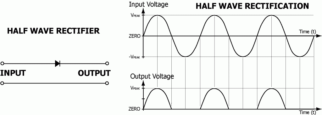
Half Wave Rectifier: a rectifier that changes only one half of every alternating current cycle into a pulsing direct current.
A single diode by itself, as drawn below, is a half wave rectifier. It lets half of every cycle pass through while blocking the other half of each cycle or wave.
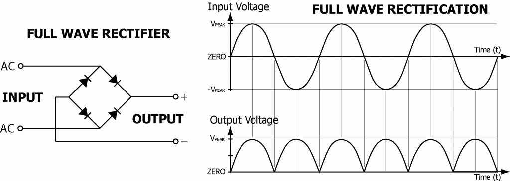
Full Wave Rectifier: a rectifier or combination of rectifiers connected in such a fashion that it changes both halves of every alternating current cycle into a pulsing direct current.
Four diodes connected as drawn below form a full wave rectifier. It lets both halves of every cycle pass through but only in the correct direction and into the correct output wire. This diode configuration is commonly known as a bridge rectifier.
Once the flow of current from an AC source has been rectified and can flow in only one direction the output voltage from the rectifier can be filtered or smoothed to whatever degree is needed.
Section 14 – CONCLUSION and REFERENCES
My purpose in writing Electrical Basics and other materials I have used in training electricians was to provide definitions, clarifications, examples, and applications of terminology, concepts, and technology used or encountered in the electrical trade.
Aside from my English dictionary, some of the technical references I used extensively in writing Electrical Basics, parts 1 and 2, included:
1. “Radio Shack Dictionary of Electronics” by Rudolf F. Graf,
2. “Alternating Current Fundamentals” by Duff and Kaufman,
3. “Electrical Principles and Practices” by James E. Adams,
4. “American Electricians Handbook” by Croft, Carr, Watt, and Summers.
5. “University Physics” by Sears and Zemansky.
Here is a Year 2009 note: Many sources of information exist today that did not exist back when I began writing these materials in the early 1980’s. So without hesitation I would add the following websites:
1. HyperPhysics: http://hyperphysics.phy-astr.gsu.edu/HBASE/hframe.html,
2. Wikipedia: http://en.wikipedia.org/wiki/Main_Page, and
3. Dictionary.com: http://dictionary.reference.com.
Joe Duncanson
Copyright © 1986 – 2011 by Joe Duncanson. All Rights Reserved.